>
Compact
linear Fresnel reflector (CLFR) power plant technology
1.
TECHNICAL AND COST FEATURES
CLFR
is a linear Fresnel reflector system with several or many linear
absorbers in the system, allowing the construction of plants in
the multi-megawatt range (Fig. 1). CLFR individual reflectors
can have the option of directing reflected solar radiation to
at least two absorbers in linear systems.
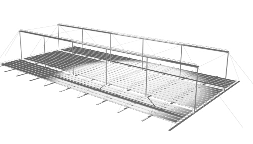
Fig.
1: Small segment of a large CLFR array showing segments of
two absorber lines. The tower height is about 15 m and typical
absorber lines will be 600 m long. (Raytrace by P. Le Lievre)
The classical linear Fresnel system has only one linear receiver,
and therefore there is no choice about the direction of orientation
of a given reflector. However, if one assumes that the size of
the field will be large, as it must be in technology supplying
electricity in the multi-megawatt class, it is reasonable to assume
that there will be many linear receivers in the system. If they
are close enough, then individual reflectors have the option of
directing reflected solar radiation to at least two receivers.
This additional variable in reflector orientation allows much
more densely packed arrays and lower absorber tower heights, because
patterns of alternating reflector orientation can be set up such
that closely packed reflectors can be positioned without mutual
blocking. The interleaving of mirrors between two linear receiving
towers is shown in Figure 2.
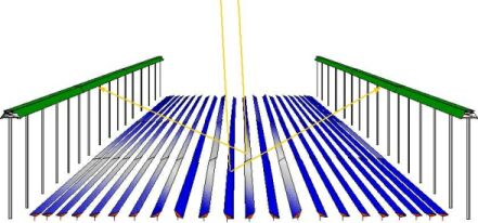
Fig.
2:
Schematic diagram showing interleaving of mirror rows to achieve
high site coverage without shading between adjacent mirrors.
The
avoidance of large reflector spacings and absorber tower heights
is an important issue in determining the cost of ground preparation,
array substructure and absorber tower structure costs, steam line
thermal losses and steam line cost. The more flexible CLFR still
delivers the traditional benefits of a Fresnel reflector system,
namely small reflector size, low structural cost, fixed receiver
position without moving joints, and the ability to use non-cylindrical
receiver geometry. But further, our CLFR power plant concept is
a serious attempt to reduce all major cost in a solar thermal
electrical system, and includes the following additional features
which enhance the system cost/performance ratio:
- The array
uses flat or elastically curved reflectors instead of costly
sagged glass reflectors. The reflectors are mounted close to
the ground, minimising structural requirements. The heat transfer
loop is separated from the reflector field and is fixed in space
thus avoiding the high cost of flexible high pressure lines
or high pressure rotating joints as required in the trough and
dish concepts.
- The heat
transfer fluid is water, and passive direct boiling heat transfer
can be used to avoid parasitic pumping losses and the use of
expensive flow controllers.
- An inverted
cavity receiver has been designed using steel boiling tubes
which can be directly linked with an existing fossil fuel plant
steam system. This is much cheaper than evacuated tubes used
in trough plants. Direct steam generation is much easier with
this absorber than with tubular absorbers in trough collectors.
- Maintenance
will be low because of ease of reflector access for cleaning,
and because the single ended evacuated tubes can be removed
without breaking the heat transfer fluid circuit.
Basic CLFR
arrangements include analogues of the east-west axis parabolic
trough, the north-south axis parabolic trough, and the polar axis
parabolic trough. Large arrays are horizontal and NS axis arrays
collect slightly more energy than EW arrays.
2. APPLICATIONS
Basic CLFR
arrangements include analogues of the east-west axis parabolic
trough, the north-south axis parabolic trough, and the polar axis
parabolic trough. Large arrays are horizontal and NS axis arrays
collect slightly more energy than EW arrays.
Retrofit
Supply of Heat to Fossil Plant
The technology
was designed for saturated steam boiling and is suitable for this
purpose up to about 365°C. An ideal market is provision of thermal
energy between 300°C and 365°C to large coal and oil fired Rankine
cycle generating plant. Approximately 100 MW(e) peak equivalent
of solar energy can be supplied to such plants for reheat alone
at 300°C, and the latter can be retrofitted to existing plant.
The CLFR
powerplant design was a winner of a A$2 million Australian Greenhouse
Office Showcase commercialisation grant and was intended be built
near Rockhampton by AUSTA Energy and Stanwell Corporation, but
this project fell into difficulty after the original project manager
AUSTA was abolished by the Queensland Government. However, due
to new legislative incentives in NSW, the project activity has
now shifted to the Hunter Valley there where a 25 MW(e) project
is planned for 2003/4 next to Liddell power station. Two other
similar sized sites have been located for future projects nearby.
The solar
array will be a direct steam generation system and will feed steam
or hot water directly into the power station steam cycle. The
first CLFR plant will be used for preheating feed water going
into the reheating circuit, although subsequent plant will be
able to be used for main boiler steam injection in to the cold
reheat line. The design steam delivery conditions for the Liddell
project are 265°C and 5 MPa wet steam.
The technology
can, in principle, allow a higher peak output per km2 of ground
area, but the current cost optimum is to be pegged at about 125
MW(e) per km2. As a comparison, an 80 MW(e) LS3 plant in California
occupies about 1.35 km2, about 60 MW(e) per km2.
The design
approach is to minimise costs by using existing power block equipment
and to maximise greenhouse gas savings by directly offsetting
coal usage. This project is particularly attractive because it
offers a low risk, low cost transitional path for commercialising
solar thermal energy. The cost of electricity is estimated to
be about $A 0.07 per kWh, close to the price of wind generation.
These costs are well below those of competing technology, and
occur for a variety of reasons.
Technology
The CLFR
will use an inverted cavity receiver containing a water/steam
mixture which becomes drier as the mixture is pumped through the
array. The steam is separated and flows through a heat exchanger
where the thermal energy passes to the powerplant system. In the
initial plant, the reheat cycle only requires steam at 265°C.
Initially
a Chrome Black selective coating will be used but a new air stable
selective coating is being developed for higher temperature operation
required by stand alone plants (320-360°C). The optical efficiency
of the receiver is very high and uses no auxiliary reflectors.
The design is in confidence.
The reflectors
are of glass slightly curved and laminated with a composite/metal
backing. Each reflector row is 600 metres long, and contains three
segments of 200 metres each of which are tracked by one motor/gearbox.
The structure is below is lightweight coated steel. Headers are
minimised, with steam down and up each receiver row. The entire
system is extremely simple and requires one laptop computer for
operation.
Costs are
kept low by using water as a heat transfer fluid, a low cost structure
with reflectors close to the ground, a low cost receiver which
is composed of mild steel pipe, and exceptionally low reflector
costs due to advanced laminated construction. The installed array
and heat exchanger cost is about $A900 peak electrical kilowatt,
about $US500. O&M is low because cleaning can be done manually
at ground level. This is less costly than an automatic cleaning
system.
3.
STAND ALONE POWER GENERATION
In NSW there
exist two regions which, although relatively small compared to
the area of NSW, make up about 100,000 km2 of relatively flat
country. In these regions, the sunlight hours are in excess of
9 hours a day on an annual basis, substantially higher than in
coastal NSW and far higher than in Europe. Currently, it is thought
that about 300 MW(e) of solar generation can be utilised from
these sites without grid extension, but the resource is potentially
enormous with grid extension. To give a sense to proportion, the
CLFR technology, working with standard steam turbine and generator
sets, could satisfy the entire electrical usage of Australia with
only 1000 km2 of such land. There exist many such suitable sites
around the world.
The CLFR can
be used with solar/gar co-firing in the initial stages to allow
lower cost. This is necessary because the power block is now about
twice as expensive as the collector field, and the power block
must be run a longer time to amortise costs. It is hoped the first
solar/gas plant can begin construction in NSW at the 100 MW level
by 2005. The unsubsidised cost is estimated at $A0.07 per kWh
initially for combined gas and solar output. Reducing the gas
fraction will raise the price.
A longer
term solution to this problem is to provide thermal storage for
the solar energy collected. This would allow the power block to
be operated on a round the clock basis, although it is likely
that a 12 hour operational period would be expected initially
because of the pool pricing of electricity. Sensible heat storage
in oil and molten salt are being considered for this line of development.
It is hoped a storage plant can be installed in NSW in about 2007.
The cost of a plant with 50% capacity factor and 80% solar fraction
(20% gas) would be close to that of the solar/gas plant above.
Eliminating the gas component would raise the cost to around 8
Australian cents per kWh. However, the extent of collector cost
reduction is not clear, and large production quantities could
lead to lower costs.
Such CLFR
technology can be installed in Europe, China, North Africa, the
United States, and in many other regions.
4.
END USE THERMAL ENERGY SUPPLY
The technology
can supply process steam up to 365°C instead of electricity. It
is suitable, with towers and receivers in scaled down form, to
provide low cost solar steam for large absorption chillers allowing
double and triple effect chillers to operate and higher temperature
ORC engines.
In this type
of application it would be similar in output to evacuated tube
systems, but may be less expensive in capital cost. It could help
run a pressurised water storage system in combination with adjacent
evacuated tube arrays. It would also be able to run more efficient
ORC turbines at higher temperatures than evacuated tube systems,
so that electricity generation would be cheaper. It also has daylighting
attributes when mounted over large spaces which evacuated tube
systems do not. But it is more complicated than evacuated tube
systems because of tracking requirements.
The system
would have a spectacular look from above, and an attractive appearance
from below as an effective daylighting device. On cloudy days
the array 'slats' could be opened up to allow more light in because
no useful power can be obtained without solar beam.
5.
UNIVERSITY WORK
The CLFR
concept was first developed in the Solar Energy Group in the early
1990's. The primary IP is now held by Solsearch Pty. Ltd. The
University is contributing optical modelling and absorber design
experience to the project, in an ongoing cooperation with the
project management company Solar Heat and Power (SHP). High temperature
selective coatings are being developed for the technology by the
University for later stand alone plants.