>
Multi
tower solar array (MTSA) technology
Since
Francia (1968) developed the first operating solar tower system,
solar tower (sometimes called 'central receiver' or 'power tower')
technology has been developed much further (Winter et al, 1991;
Kolb et al, 1991; Grasse, 1991). A typical solar tower power system
consists of a field of two-axis tracking reflectors, called heliostats,
which focus the direct solar radiation onto a tower-mounted receiver.
The heliostat field is a special kind of Fresnel reflector which
has performance limitations due to mutual blocking and shading
of the heliostats. These limitations of a heliostat field were
first derived by Riaz (1976).
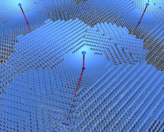
Figure
1. Visualisation of appearance of one of the MTSA towers (by Schramek).
The
Multi Tower Solar Array (MTSA) is a new concept of a point focussing
two-axis tracking concentrating solar power plant (Fig. 1). The
MTSA consists of several tower-mounted receivers which stand so
close to each other that the heliostat fields of the towers partly
overlap. Therefore, in some regions of the total heliostat field
the heliostats are alternately directed to different aiming points
on different towers. Thus the MTSA uses radiation which would
usually remain unused by a conventional solar tower system due
to mutual blocking of the heliostats.
The configuration of the heliostat field of an MTSA can be optimised
to get a high annual efficiency for using the available beam energy
which would otherwise strike the ground or roof below. In the
regions close to the towers, where the shading effect predominates,
all heliostats are directed to the nearest tower. In regions further
away from the towers, the heliostats are alternately directed
to two, three, or four aiming points on different towers.The MTSA
approach reduces the losses occurred by mutual blocking of the
heliostats more distant from the towers.
A
heliostat field with a high density of heliostats can transfer
radiation onto a tower mounted receiver with almost the theoretically
maximum performance. However, this means a low utilisation of
the installed reflector area due to blocking and shading. Therefore,
the heliostats close to the tower of a conventional solar tower
system are spaced apart to avoid mutual shading. Heliostats more
distant from the tower are spaced apart, so that they do not block
each other. Direct solar radiation falls onto the ground, instead
of being reflected from costly reflector area uselessly upon the
backside of the reflector of another heliostat.
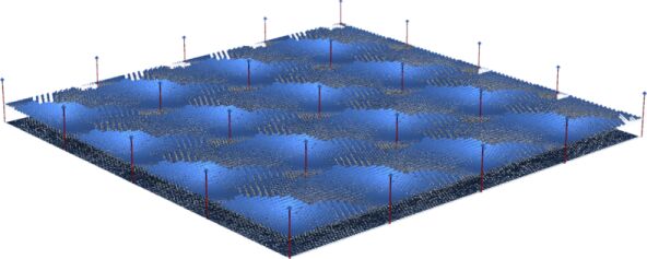
Figure
2:
An array of MTSA towers.
The
proposed Multi Tower Solar Array (MTSA) consists of a group of
solar towers where the heliostat fields of the towers partly overlap,
similar to the operation of the linear CLFR (Fig. 2). For an MTSA,
where the heliostat fields of up to four towers can overlap, the
situation becomes more complex, because in some regions the neighbouring
heliostats might be alternately directed to the aiming points
on more than two different towers. In some regions, especially
close to one of the towers, all heliostats are directed to only
one aiming point, in other regions the heliostats are alternately
directed to two, three or four aiming points on different towers.
The overlapping heliostat fields of a Multi Tower Solar Array
increase the Annual Ground Area Efficiency and the Annual Reflector
Area Efficiency substantially in contrast to conventional solar
tower systems with a single central receiver, which means a more
efficient usage of the solar radiation falling on a given ground
area. On the one hand, this allows to set up a solar power plant
for a specific output on a smaller ground area, or on the other
hand to set up a solar power plant with a higher output on a given
ground area. This consequently means savings in construction and
land costs per installed capacity of the solar power plant. Additionally
an MTSA with small towers and small heliostats can be set up in
an urban environment over large parking lots or on flat roofs
of big buildings, since urban applications need to use the given
ground or roof area efficiently. Over 90% of the annual beam radiation
falling on the ground or roof can be used with a practical array.
In this way the advantages of concentrating solar power plants
can be used in the urban environment.
COMBINED HEAT AND POWER and BEAM SPLITTING
The
MTSA is a highly space efficient concept with several possible
market niches, but we wish in particular to address possible generation
of concentrating solar power in or near urban environments. It
is ideal for restricted roof or over parking lot spaces. An initial
thought was to develop this using separate high efficiency PV,
thermal, and methane/hydrogen (reforming) receivers but it is
now pssible to design beam splitting panels of negligible optical
loss to separate the incoming beam into two spectral portions,
one of which is suitable for PV and the other for thermal purposes.
Beam splitting is useful because a PV receiver uses only photons
above a certain energy. Within this range the PV can potentially
be more efficient than any likely heat engine. The remaining photons
can be used by a thermal receiver without sacrificing its thermodynamic
potential. The thermal receiver is sensitive to total energy supplied
and can make full use of the split-off lower energy photons. In
combination, very high conversion efficiencies are possible (>30%).
However, only high optical concentration can be used, because
concentrating PV receivers are very expensive and because the
thermal receivers are more thermally efficient under high concentration.
This suggests that high concentration systems are likely to prevail
in the long run because overall electrical output efficiency can
be much higher than in any low or non-concentration system. However,
access to beam splitting technology is essential
to access this option.
Both dishes and tower systems like the MTSA could use this approach
and achieve similar efficiencies of conversion. However, dish
arrays are less space inefficient than MTSA. The MTSA can use
also larger heat engines than dishes and these can be fixed in
place, a significant practical advantage. As for the size of the
systems, there is no advantage to constructing large PV receivers
but there are strong size restrictions on the size commercially
available heat engines. For small gas turbines under development,
resulting tower size for initial urban applications is likely
to be below 10 metres. With hydrogen receivers, efficiency grows
with reformer receiver size but 10 metres will result in a reformer
receiver size much larger than the current CSIRO unit. An international
cooperation between Australia, Italy, Germany and Israel is forming
at this time to develop this approach.
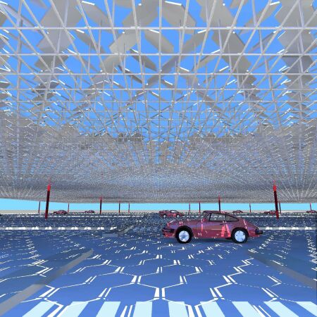
Figure
3: Impression of conditions in a parking lot topped by an
MTSA solar array.
REFERENCES
Francia, G.(1968) Pilot Plants of Solar Steam
Generation Systems. Solar Energy 12, 51-64 Grasse, W. (1991) PHOEBUS
- international 30MWe solar tower plant. Solar Energy Materials
24, 82-95.
Karni J. and Ries H. (1994) Concepts for High
Concentration Primary Reflectors in Central Receiver Systems.
In Proceedings of the 7th International Symposium on solar Thermal
Concentrating Technologies, Vol.4, pp. 796-801, Moscow, Russia.
Kolb, G.J., Alpert,D.J. and Lopez, C.W.(1991)
Insights from the operation of Solar One and their implications
for future Central Receivers Plants. Solar Energy 47, pp.39-47.
Mills D.R. and Morrison G.L. (2000) Compact Linear
Fresnel Reflector solar thermal powerplants. Solar Energy 68,
263-283.
Riaz, M.R. (1976) A Theory of Concentrators of
Solar Energy on a Central Receiver for Electric Power Generation.
ASME Journal of Engineering for Power 98, 375-384.