Material Dispersion Winfield
Defining material dispersion in winfield’s structure editor:
- Create a new material
- Select the type and order of expansion and enter its coefficients
- Select the material for the background, cladding, jacket or cylinders as appropriate using the drop down lists.
Contents
Creating a new material:
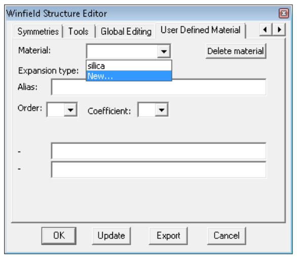
Go to the User Defined Material tab in the structure editor dialog. In the material drop down list select New...
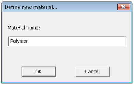
A new dialog appears. Enter the material’s name, which should not be numbers only and should not contain spaces.
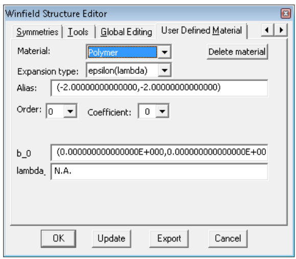
Click Ok. The User defined material tab now becomes something like this:
You don’t need to worry about the complex number in Alias, unless this number corresponds to the exact value of a complex permittivity of a dispersionless material you want to use in other parts of the structure, which is extremely unlikely.
Choosing the appropriate expansion, expansion order, and entering the coefficients
The expansion type is selected in the ‘Expansion type’ drop down list. The order of the expansion is defined with the order drop down list. Different expansion types are available, and each expansion type requires one or two coefficients per term of the expansion. These are entered in the two text boxes (in figure above there are labelled b_0 and lambda_0) for each term of the expansion. The term of the expansion (from 0 to the order of the expansion) for which coefficients are modified is selected through the ‘coefficient’ drop down list. After selecting the appropriate expansion, its order and after having entered all the coefficients (by succesvily going through all the values of the ‘coefficient’ drop down list). Click ‘update’ and ‘export’ to save the structure.
The available expansions are:
Sellmeier type expansions
These take a form similar to
Which can also be expressed in terms of wavelengths, and sometimes are used to express the refractive index directly (rather than the permittivity). For each term i of the expansion there are thus two constants to enter, ωi (or λi) and bi . The index i ranges from 1 to the order of the expansion. Coefficient 0 is used to add a constant value to the expansion (which is not technically part of a sellmeier expansion, but can be useful when one wants to add a constant index step to an existing material dispersion).
In the cudos mof utilities, the following expressions are available:
- a. Epsilon(lambda)
In that case the relative permittivity is expressed as
Where λ is in the same unit as the dimensions of the fibre (typically micrometers).
- b. Epsilon(omega)
In that case the relative permittivity is expressed as
Where ω is the angular frequency, converted from the wavelength through ω=2πc/λ . Beware that in this conversion c is in m/s, so λ as given in the parameter file is assumed to be in meters. This means that when using the formula as such, dimensions in the structure file should be expressed in meters too.
- c. n(lambda)
In that case the refractive index is expressed as
Where λ is in the same unit as the dimensions of the fibre used in the structure file (typically micrometers).
- d. n(omega)
In that case the permittivity is expressed as
Where ω is the angular frequency, converted from the wavelength through ω=2πc/λ . Beware that in this conversion c is in m/s, so λ as given in the parameter file is assumed to be in meters. This means that when using the formula as such, dimensions in the structure file should be expressed in meters too.
Cauchy expansion
Cauchy expansions can be used by choosing the Cauchy expansion option. The refractive index is then expressed as (for versions of fibre 2.1.0.3 and later)
Another expansion, similar to the Cauchy expansion is sometimes found in data sheets, defining the refractive index rather than the permittivity. This type of expansion can be used by n[lambda power expansion], which defines 'n' as
Where λ is in the same unit as the dimensions of the fibre used in the structure file (typically micrometers).
Polynomial expansion
The refractive index can be expressed as a polynomial function of the wavelength. While this is useful to represent the refractive’s index dependence as a function of wavelength through interpolation of experimental data, polynomial expansions are a poor choice when material dispersion is strong, or when wide wavelength ranges are used. Also one has to be extremely careful to use polynomial interpolation exclusively within the range of the initial data points to which the polynomial has been fitted, as outside this range polynomials (espetially higher order polynomials) tend to diverge very rapidly. Polynomial expansion are obtained using the n[lambda polynomial] option in the expansion drop down list. The refractive index is then expressed as
Where λ is in the same unit as the dimensions of the fibre used in the structure file (typically micrometers).
Resonator model
Using a simple (or not so simple) classical oscillator model a number of expressions can be derived for the permittivity of materials [Kroon 2007]. The current implementation of the software allows to use an expression valid for insulator or semi-insulating semiconductors, with some phonon damping. The expression is
where ![]() is the longitudinal phonon resonance frequency,
is the longitudinal phonon resonance frequency, ![]() is the transverse phonon resonance frequency,
is the transverse phonon resonance frequency, ![]() is the phonon damping factor,
is the phonon damping factor, ![]() represents a constant dielectric background due to the bound electrons, and
represents a constant dielectric background due to the bound electrons, and ![]() = (1/λ) is the wave-number. In winfield, the parameters are entered as follows:
= (1/λ) is the wave-number. In winfield, the parameters are entered as follows:
Accordingly, the order of the expansion has to be set to at least 3 (higher order coefficients are ignored).Using the oscillator model with an order of expansion less than 3 will lead to runtime errors.
Note that the current implementation contains conversions for ![]() and
and ![]() and
and ![]() to be expressed in (1/cm) and λ to be expressed in micrometers. More specifically, the actual implemented formula is
to be expressed in (1/cm) and λ to be expressed in micrometers. More specifically, the actual implemented formula is
Here λ is expressed in micrometers (which assumes all dimensions of the structure file are also in micrometers).
Note that the Drude model is a special case of the resonator model, with ωT=0 and ωL=ωp/ε∞1/2. The resonator model can thus be used for materials described by the Drude model. However, a specific implementation of the Drude model, with parameters in SI units, is also available, see below.
Drude model
A simple Drude model with damping describes the permittivity of most metals quite accurately, especially away from the plasma frequency and from possible interband transitions (in particular the model is not appropriate for gold and copper in the visible...). The permittivity is then given by
where in Winfield the parameters are entered as follows (the name of the parameters appears in the winfield window instead of b_0, b_1,c_1, but the expansion order has to be 1 to access the parameters).
this assumes all dimensions and wavelengths in the structure and paramter file to be expressed in micrometers, as usual.
No material dispersion
In this case the permittivity takes a constant value, defined as b_0. The order of the expansion should be set to zero, and the value of the relative permittivity entered as the b_0 coefficient.
Using a user defined material
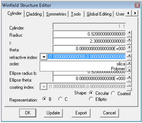
Once one or several user defined materials have been defined, they appear in all drop down boxes defining refractive indices. For example if a material called polymer has been defined, the drop down list for the refractive index for each cylinder will look like this. If Polymer is selected, the cylinder will take the wavelength dependent refractive index of that material.
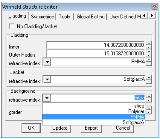
Cladding, jacket and background materials can also have user defined dispersion properties, as in this example below where we have defined three materials called PMMA, Polymer and SoftglassA
Note that a constant complex value can also be entered in these drop boxes instead of choosing a user defined material.
Tips and tricks
Re- using materials:
You can define as many materials as you want. The definitions of materials are saved in the structure file; to re-use previously defined materials for a new structure, just start the new structure by opening your existing structure file and use the lattice generator (in the symmetry tab) and editing tools (Tools tab and global editing) to create your new structure.
Accessing User defined materials indices in parameter files
In a parameter file, the name of a user defined material will be evaluated to the value of the automatically. Indeed one often wants to find mode with effective indices closes to that of the background index, and to avoid numerical artefacts, division by zeros and semi-infinite loops one should avoid having an effective index window covering refractive index values of any of the structure’s refractive indices (cf. user’s guide).
Example: in your structure file you have defined a material called PMMA. The structure is a fibre with holes in a PMMA background. The lowest order core modes will have effective index close to but below the refractive index of PMMA. In your parameter file you can define the effective index window using:
- lambda=0.8
- n_eff_0=PMMA-0.01
- upper right n_eff corner=[PMMA-(1e-6,0)]+(0,1e-1)
This will select the following effective index region, defined using the refractive index of PMMA at a wavelength of 0.8μm.
Later in the same parameter file, one could have
- lambda=0.9
- n_eff_0=PMMA-0.01
- upper right n_eff corner=[PMMA-(1e-6,0)]+(0,1e-1)
which will adapt the effective index region to be
Note that the expressions are evaluated at the currently defined wavelength. If no wavelength has been defined earlier in the parameter file, the returned value will be random.
In combination with macros, this allows the simplification of parameter files for the search for modes at different wavelengths when using material dispersion. For example if we create a file defineneffandsearch.txt containing
n_eff_0=PMMA-0.01
upper right n_eff corner=[PMMA-(1e-6,0)]+(0,1e-1)
search modes
exit
We could automatically search for modes at different wavelengths with a parameter file similar to the following:
- load structure=mystructure.mof
- load=commoparameters.txt
- lambda=0.8
- file name radix=modes08
- load=defineneffandsearch.txt
- lambda=0.9
- file name radix=modes09
- load=defineneffandsearch.txt
- lambda=1.0
- file name radix=modes10
- load=defineneffandsearch.txt
- end
Where thresholdvalues.txt is a text file defining common parameter values (eg start mode, stop mode, eigenvalue threshold, accuracy goal etc.).
Checking the expressions
To check that you’ve entered the correct expression, you can check the *_results.txt file, which contains a list of all user defined materials, with their expression, values of coefficients, and value of the refractive index at the current wavelength.
When calculating dispersion curves using the dispersion keyword, the file *_matdisp.dat contains columns with the complex refractive index of all defined materials at all wavelengths points included in the dispersion simulation.
Resources
To download a pdf version of this page (which is the unedited original prior to MediaWiki CUDOS site being set up), click: Media:Defining material dispersion in winfield.pdf
