Scattering simulations
The CMU can simulate scattering off any structure that can be defined with winfield, in normal or oblique incidence, calculating the scattered fields as well as the scattering or differential cross sections. No symmetries can be taken into account (most often there are none anyway, because the incident light breaks the symmetry), with the incident field being a plane wave (or approximation thereof, which resembles more a Gaussian beam than a plane wave, due to the plane wave ebing approximated by a finite sum of Bessel functions - the size of the region over which the field is a good approximation of a plane wave depends on the parameter gorder of the structure file, which should be set large enough for the wave to be a reasonable plane wave over the entire size of the structure). The software also calculates the scattering cross section and the quantity \rho_fb defined by White et al in Opt. Lett. 27 (22) pp 1977-1979 Eq. (2). The software can process a list of different incident angles and wavelengths in one go.
Contents
Limitations
For fibre versions 2.1.1.2 and earlier, simulations with a single with a cladding and jacket are not possible; no error message is produced. Simulations with one or multiple coated cylinders will give correct scattering cross section results and fields outside the cylinder, but fields within the coatings will be artificially set to zero.
From version 2.1.1.3 fields are calculated correctly for coated cylinders. Scattering simulations with a single cylinder and a cladding and jacket are still not possible, but an error message is generated.
Keywords
The relevant keywords are
load angle file=anglefilename
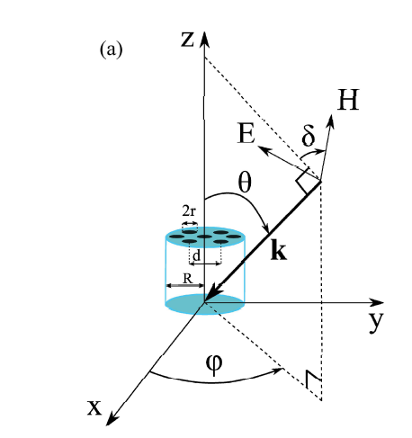
loads a file containing the list of wavelength and incident angles to be used. The format of the file should be 4 space separated columns containing lambda, theta, phi, delta with lambda the wavelength, theta, phi and delta the incidence and polarization angles as defined in the Figure below:
If a single angle and wavelength are of interest, the parameters can also be defined with the following keywords:
theta=angle
phi=angle
delta=angle
and the wavelength being defined by the usual 'lambda' keyword. Note that angles are to be real.
numbserpoints=number of points
defines the number of points to be used in the integral for \rho_fb, as well as the number of points on which the differential cross section is to be computed. This keyword is mandatory before the simulation can be used. A synonym is integral resolution. Calculating the integral is numerically fast, and 1000 points or higher is a safe number to use to ensure accuracy.
diffract
runs the simulation, running one scattering simulations for each line in the angle file, in which the wavelength, polarization and agnle of incidence are defined.
Results
The software writes a bcf/fbb file per line of the angle file, as well as a *_ser.txt file containing the angular differential cross section. The unique *_rhofb.txt file contains a list of wavelength (col 2) theta, phi, delta (col 3-5) rho_fb as defined by White et al (col 6) and total scattering cross sections for E and H (that is, for both polarizations, when relevant) - in most papers the cross-section is the sum of both. Cross sections are normalized by the diameter of the first cylinder in the structure file.
Winfield
When opening an fbb or bcf file from a scattering simulation, winfield can display the incident, scattered or total field. The corresponding options are in the 'View' menu, anre are incident only, scattered only and normal respectively. As for other bcf/fbb files, when opening the file the default field component displayed is the Poynting vector component S_z. For most scattering simulation this field component is irrelevant, and typically Ez and Hz (when non-conical incidence is used) or other E/H components will be more relevant.
Scattering and differential cross sections
The scattering cross section is the hypothetical area normal to the incident radiation that would geometrically intercept the total amount of radiation actually scattered by a scattering particle.
The differential cross section (also often called radar cross section ) is the scattering cross section for scattering in one specific direction.
For two dimensional problems in normal incidence, the differential cross section takes unit of length and is defined as
where k is the wave vector of the incident light, A is a vector describing the polarization, M described the direction away from the object in which the scattering cross section is considered, Wd is the power density of the scattered wave in direction M at a distance r (where it can be considered a plane wave, when r goes to infinity), and W0 is the power density of the incoming plane wave.
For electromagnetic waves in normal (ie not conical) incidence one has
where Ed is the amplitude of the diffracted electric field at a distance r away from the origin, E0 the amplitude of the electric field of the incident plane wave. The differential cross section depends on the angle of incident and can be defined for all scattered angles (Ed is taken in a specific direction).
See also wikipedia article on Radar Cross Sections
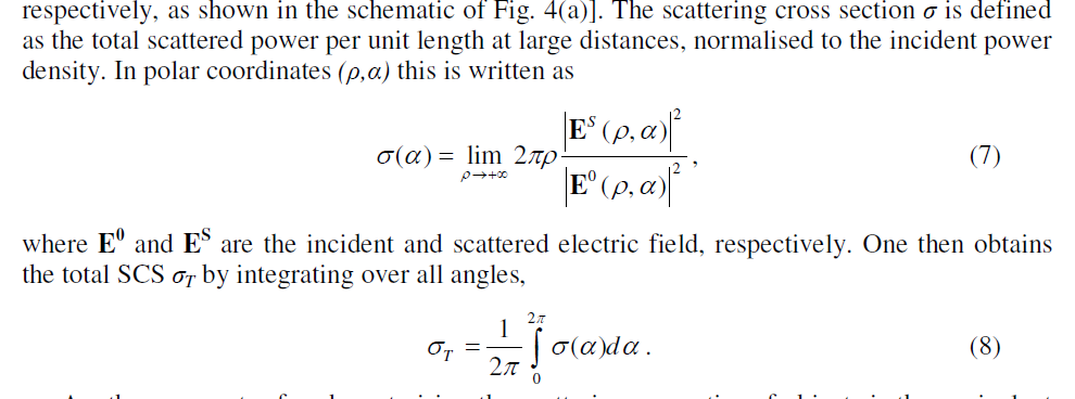
The total scattering cross section is obtained by integrating the differential cross section over all scattering angles:
(From A. Tuniz et al, Optics Express 18(17) pp.18095-18105 (2010).
Sample files
See the Example repository.


